| Tutorial >> The Remote Laboratory Interface |
|
The user begins by interactively constructing and configuring a network of NSPs, hosts and links using the Topology menu. This activity can involve:
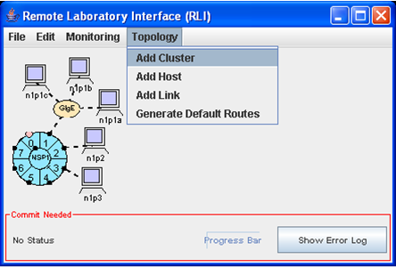
Fig. 1 shows the main RLI panel during the configuration phase with its main drop-down menus at the top. The user has just added a cluster using the Topology => Add Cluster menu. The links are shown as dashed lines, and the hosts and NSPs are shown in light shade indicating that the objects have not yet been bound to actual testbed resources. A cluster consists of an NSP, a gigabit Ethernet subnet with three more hosts connected to port 1, two hosts directly connected to ports 2 and 3, and a CP connected to port 0.
Note that before resource allocation, hosts and NSPs have only logical names. Host naming follows the notation nXpY where X indicates the logical NSP number and Y indicates the port number. So, n1p2 refers to the host attached to port 2 of NSP 1. After resource allocation, objects retain their logical names but also acquire actual (or physical) names (e.g., onl20.arl.wustl.edu).
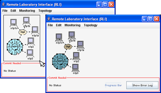
Icons can be treated as a group by dragging a rectangle with the mouse. The members of the group are shown in a darker shade. The group can be dragged by grabbing onto one of the icons (e.g., host). The group can be dissolved by clicking in an open area of the window.
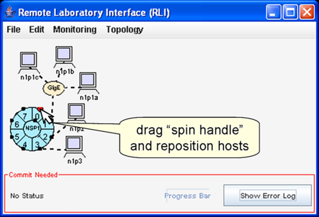
An NSP icon can be rotated or spun by selecting port 0 with the left mouse button. When port 0 is selected, it turns from pink to red. Visually appealing topologies with multiple NSP configurations can be constructed by spinning NSPs and moving hosts to avoid confusing link crossings.
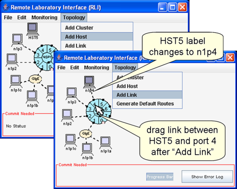
Additional hosts can be added and linked to other ports by selecting Topology => Add Host and Topology => Add Link. In Fig. 4 left, we have added host HST10 on the left. Then, in Fig. 4 right, we have added a link from port 4, NSP1 to the new host on the right by selecting Topology => Add Link and then dragging from the left mouse button from port 4 to HST10.
The Topology => Generate Default Routes menu item is used to initialize the NSPs' routing tables so that packets sent to any host will be routed to it along some minimum hop path. By default, the route tables at each ingress port are empty. Typically, although not necessarily, we generate default routes at all of the ingress ports and then add more specific route entries as necessary. As will be shown later, a route table can be changed by selecting a route table item at a specific port.
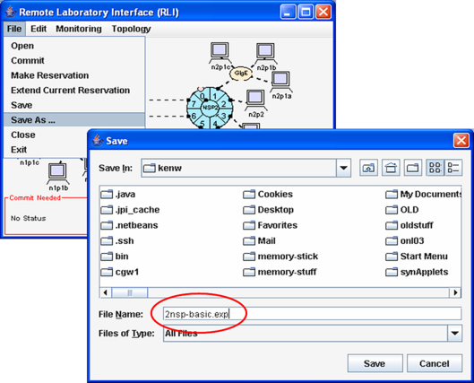
In Fig. 5, we select File => Save As to save the current configuration to a file. A dialogue box allows us to name the file where the configuration should be saved. A configuration can be saved at any time, even before requesting that resources be allocated for the network.
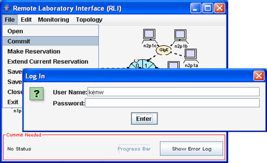
We selected File => Commit to allocate and initialize physical resources in the testbed. This causes the RLI to send a commit message to the configuration daemon. The configuration daemon attempts to allocate the physical resources and configure them to match the user's network. A progress bar is shown at the bottom. If any error occurs, an error log window will be displayed. The error log can also be shown at any time by selecting the Show Error Log button at the bottom right hand corner of the display.
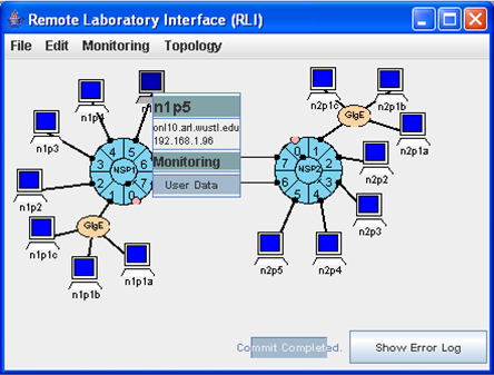
When the configuration daemon has finished, the red Commit Needed border around the status bar disappears. Assuming the requested resources are available, the RLI display will be adjusted as shown in Fig. 7. Note that the links are now shown as solid, black lines and the other objects are displayed in a darker blue color signalling that the components are now bound to actual hardware resources. The names and IP addresses of each host can be determined by right-clicking on the host. Here, host n1p5 has been assigned to onl10.arl.wustl.edu and the network interface address 192.168.1.96 has been assigned to the interface leading to NSP1's port 5.
As indicated earlier, each host has two interfaces. One has an internal name (e.g., n1p2) and the other an external name (e.g., onl10.arl.wustl.edu) that can be used to open SSH connections to the host for the purpose of running applications. The IP address shown in the RLI display is the address assigned to the host interface that is internal to the testbed and will carry your data traffic. These addresses are not externally visible, and like the internal names are assigned algorithmically, making it possible to repeat an experiment in different sessions without having to modify names and addresses used in demonstration scripts.
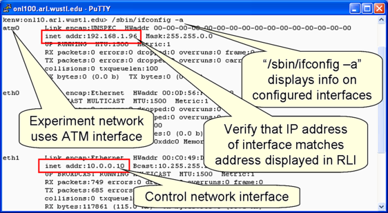
We logged into onl10.arl.wustl.edu using ssh and ran the /sbin/ifconfig command to verify that the internal network interface address was in fact 192.168.1.96 as reported by the RLI. As you may have guessed by now, the internal IP address is generated by an algorithm that sets the first two octets to 192.168, sets the third octet to the logical NSP number, and sets the last octet to 16 times one more than the port number (48 = 16 * (2+1)). Note also that the internal network interface attached to all ports except port 1 is atm0. Since Port 1 is attached to a gigabit Ethernet interface, its internal interface is eth1 instead of atm0. The external interface is the Ethernet interface eth0 which carries control network traffic.
ONL hosts run the Linux operating systems, and the default command interpreter is the bash shell. Here is one way to run the above command and a ping command:
1.  client>  ssh onl.arl.wustl.edu	# ssh to ONL user host
2.  onlusr>  ssh onl10			# ssh to n1p2 host
3.  onl10>   /sbin/ifconfig		# show network interface properties
Here is an explanation of each line:
Here is an alternative recipe that uses the .topology file described in RLI Basics:
1.  client>  ssh onl.arl.wustl.edu	# ssh to ONL user host
2a. onlusr>  source ~onl/.topology	# use ~onl/.topology.csh if using a C-shell
2b. onlusr>  ssh $n1p2			# $n1p2 will evaluate to onl10
3.  onl10>   /sbin/ifconfig		# show network interface properties
Line 2a defines environment variables of the form $nXpY for all control network interfaces of the user's committed hosts. In our example, $n1p2 will evaluate to onl10 in Unix command lines since it is the control network interface corresponding to the host labeled n1p2 in the RLI. This allows us to write shell scripts that survive experiment shutdowns, and reduce the need for clicking on hosts in the RLI to discover their control network interface names.
Revised: Fri, Oct 27, 2006
| Tutorial >> The Remote Laboratory Interface |
|