| Tutorial >> The Remote Laboratory Interface |
|
Each NSP ingress port has a route table that is used by the FPX to decide where to forward packets. The route table stored in the FPX uses an efficient tree bitmap structure for fast packet classification with efficient memory usage. The longest prefix match algorithm employs multibit trie data structures that are ideally suited for a fast hardware implementation.
All private (internal) IP addresses have 192.168 as their first two octets. The third octet indicates the NSP number (e.g., 1, 2). The internal network interface (atm0) of hosts attached to ports 2-7 have the last octet equal to 16 times one more than the port number. So, the atm0 interface on host n1p3 (NSP1, port 3) has 192.168.1.64 as its IP address. Since there are three hosts attached to port 1 (the gigE interface), their IP addresses start consecutively at 192.168.N.32 (i.e., 192.168.N.32, 33, 34) where N is the NSP number.
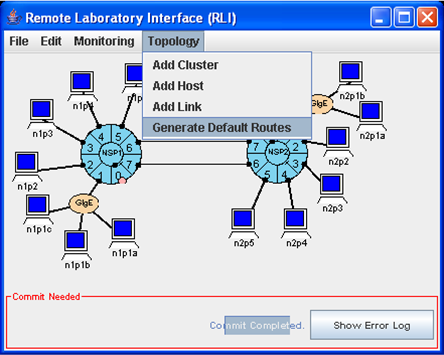
By default, the route tables are empty. The Topology => Generate Default Routes menu item (Fig. 1) can be used to generate default route tables at all of the ingress ports. These route entries allow packets to be forwarded to the other six ports of the local NSP and other attached NSPs.
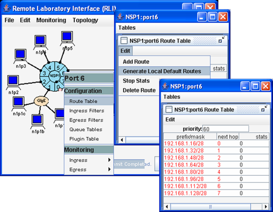
But the user can also choose to generate a default routing table at only a single port by left-clicking the port of interest. The route table in Fig. 2 shows the prefix/mask entries for forwarding to the next hop NSP 1, port P as 192.168.1.m/28 where m = 16 * (1 + P) for P = 0..7. Only the first 28 bits of the destination IP addresses of hosts that are local to the NSP need to be examined to determine the next hop since the fourth octet only differs in the first four bits from port to port.
A route table can be modified by selecting an entry field and changing that part (e.g., next hop). The Route Table => Edit menu allows the user to add a route, generate default routes, stop statistics and delete a route.
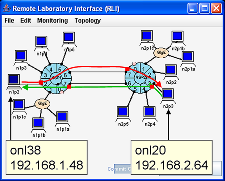
Consider, for the moment, what is required for host n1p2 to communicate with host n2p3 (i.e., one host of NSP1 to communicate with one host of NSP2). First, Fig. 3 shows that the two physical links between the two NSPs can be used. Second, traffic from n1p2 can only reach n2p3 if there is a proper route table entry at each ingress port encountered along the path from n1p2 to n2p3. Using the notation N.P to refer to NSP N, port P, the port path from n1p2 to n2p3 through the upper inter-NSP link is: 1.2, 1.6, 2.7, 2.3. But the only ports in this list which use the ingress side are 1.2 and 2.7. So, the route (forwarding) tables at ports 1.2 and 2.7 must be properly configured to allow traffic to flow over the top link from left-to-right. In a similar fashion, the forwarding tables at ports 2.3 and 1.7 must be properly configured to allow returning traffic to flow over the bottom link from right-to-left.
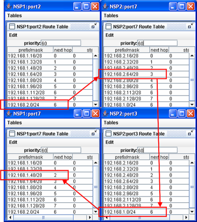
It is easy to setup the two-way communication path shown in Fig. 3 by generating the global default routes using Topology => Generate Default Routes. The relavent route tables and entries are shown in Fig. 4. After specifying the new route entries, remember to actually install the routes by selecting File => Commit.
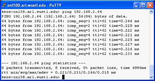
Fig. 4 shows that host n1p2 can ping host n2p3. Since ping sends ICMP echo request packets to a destination host and the destination host responds with ICMP echo reply packets, successful ping traffic indicates that there are proper route entries for two-way communication.
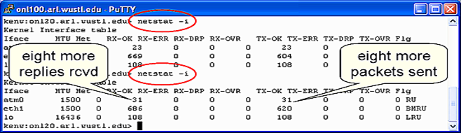
Fig. 6 shows how you can use the Unix command netstat -i to verify that the proper number of ICMP echo request packets were received at and ICMP echo reply packets were sent from the destination n2p3. We SSH'd to onl20 (the control network interface associated with n2p3) and ran netstat -i before and after the ping was run. The ping command was terminated by entering ctrl-c after eight ping messages. The netstat command window shows that the ATM (atm0) interface had received (RX-OK) and transmitted (TX-OK) 23 packets before ping was run and received and transmitted 31 packets after the ping was run; i.e., eight additional packets. The next section will show how you can verify that traffic is indeed flowing over the desired links (ICMP echo requests on the top link left-to-right and ICMP echoreplies on the bottom link right-to-left).
Revised: Thu, June 29, 2006
| Tutorial >> The Remote Laboratory Interface |
|