| Tutorial >> The ONL Architecture |
|
Normally, packets arrive to an FPX at an input port and eventually exit from an output port after some processing at an FPX. An input port is primarily concerned with efficiently forwarding packets to the output port. In contrast, an output port is primarily concerned with scheduling the transmission of packets out of an output line card. This page first describes generally how packets flow through an NSP. Then, it describes how plugin processing fits into the packet processing at an input port and illustrates how packets are directed toward plugins by an FPX. Then, it describes how plugin processing fits into the packet processing at an ouput port. The descriptions are presented at a fairly high level providing just enough information to understand some of the details of plugin construction discussed later. The details can be found in the FPX design document .
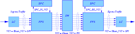
Fig. 1 shows the logical components that may be involved in transfering a packet from an input port to an output port of an NSP. The fast path from input to output is straight through; i.e., LC-FPX-SW-FPX-LC. Customized packet processing is provided by plugins that are loaded into SPCs located at inputs and/or outputs. In order to have packets processed by a plugin, a filter must be configured to direct the packets to the plugin. A simple path through an input-side plugin would be LC-FPX-SPC-FPX-SW-FPX-LC; i.e., the packet goes from the FPX to the SPC and then back to the FPX for reclassification. Since the core of an NSP is an ATM switch, packets are carried across an NSP as AAL5 frames on specific Virtual Circuit Identifiers (VCIs).
A logical block diagram of the hardware components of the NSP is shown in Fig. 2. Note that both ingress and egress traffic share a single datapath. All traffic arrives at the Input Segmentation and Reassembly (ISAR) block in the form of AAL5 encapsulated frames. The ISAR extracts the payload of the ATM cells of the AAL5 frames, which includes the Internet and Transport protocol headers. The cells of frames arriving from 14 different VCIs (four virtual interface VCIs, the eight switch port VCIs, and two SPC VCIs) may become interleaved. Therefore, the ISAR must maintain a total of 14 reassembly contexts. The ISAR must insert an NSP Shim for traffic arriving from the line card. The shim is an internal packet header used to communicate information regarding packet handling throughout the NSP. The ISAR buffers then writes fixed size chunks of arriving packets to the Packet Storage Manager (PSM).
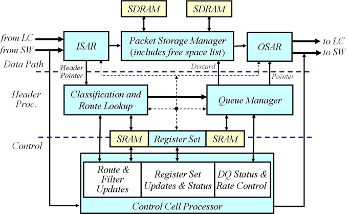
Fig. 2. Logical Block Diagram of an FPX RAD.
Once the entire packet has been received in the ISAR, the packet pointer, shim fields, and packet header fields are forwarded to the Classification and Route Lookup (CARL) block for classification. Upon completion of a lookup, CARL updates the shim fields and, if necessary, makes copies of the packet header fields. This will occur in the case of multicast packets or a non-exclusive filter match. Note that only one copy of the packet is stored in SDRAM, while multiple copies of the packet header may exist.
The packet pointer, packet length, copy count, and shim fields are sent to the Queue Manager (QMGR). Based on the shim fields, the Queue Manager decides which queue to place the packet on. The Queue Manager (Fig. 3) schedules packet transmission according to parameters for each type of queue. Parameters range from packet length to rates distributed between ports in control cells received by the CCP.
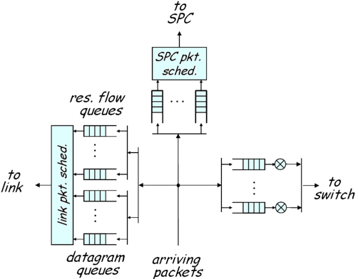
The QMGR supports 510 queues. Queues are identified by their Queue Identifiers (QIDs). There are 127 queues destined for the SPC, 127 queues returning from the SPC, 8 ingress datagram queues, 64 egress datagram queues, and 184 other reserved flow queues shared between the ingress and egress sides of each port. Note that both qid 0 and its complement qid 128 are not used. The QID assignments are:
The packet pointer, shim fields, and copy count of the next packet to be sent is forwarded to the OSAR. The OSAR retrieves the packet from the PSM, creates an AAL5 frame, and transmits the cells of the frame on either the RAD switch or line card interface. Note that cells of a frame cannot be distributed across the two interfaces to prevent reordering. The OSAR must also remove NSP Shims from the header of packets transmitted on one of the four virtual interfaces (LC). For packets with copy counts greater than one, the PSM must keep track of how many copies of the packet have been sent.
Note that control cells are switched to the control path at the input of the ISAR and processed by the Control Cell Processor (CCP). The CCP is responsible for managing the packet classification database, register file, and queuing parameters. Response cells are switched into the datapath at the outputs of the OSAR block.
There are packet counters associated with the filters and Route Table entries. The GM Filter counters are only incremented when the filters win the priority resolution and are applied to the packet. Counters in the Route Lookup and Flow (EM filter) Tables are updated when an entry is matched (prior to priority resolution).
We now describe some more details of packet processing at an input port. The FPX performs the standard packet processing steps and leaves the plugin processing to the SPC. If a packet requires plugin processing, the FPX sends the packet or the packet header to the SPC over a special VCI (62) (VCI 63 is used on the egress side). The same VCI is used by the SPC to send packets (or packet headers) back to the FPX. The main packet processing steps at the FPX are:
Step 3 is skipped when packets do not require customized processing.
Step 1 (Shim and IP Header):
The FPX prepends a shim to each packet (IP datagram) that arrives at an input and then applies the standard set of IP packet header processing operations to the packet. For example, the TTL (Time-To-Live) field is examined, and the packet is dropped if the TTL field reaches 0. The FPX will remove any shim at an output before sending it to the ouput line card. Data packets are AAL5 frames with an MTU of 2,000 bytes excluding the shim. The shim is used to communicate information between NSP components (FPXs and SPCs). The format of the shim depends on whether the packet is traveling within a PP (Port Processor) or between PPs. An intraport shim is used to communicate between an FPX and its SPC partner at a PP, and an interport shim is used with a packet traveling from an IPP (Input PP) to an OPP (Output PP).
Fig. 4. Intraport Shim.
An intraport shim (Fig. 4) is 16 bytes and is used to send inband control information between components within a single packet processor (e.g., from an FPX to an SPC). The intraport shim contains eight fields, but the ones of most interest to the plugin programmer are the OVIN, the Queue Identifier and the flags. The Output Virtual Interface Number (OVIN) indicates the output port where the packet should be forwarded. The Queue Identifier (QID) is a label that identifies the need for plugin processing or reserved flow processing. In the FPX, there is a hardware queue associated with each unique QID. Whenever an IPP plugin modifies one of the five packet header fields used in classification, it must notify any attached FPX so that the packet can be reclassified before being forwarded since the OVIN and QID fields of the intraport shim and the OVIN of the interport shim may need to be changed. Finally, the flags field contains eight bits that indicate such things as whether the packet needs to be reclassified by the FPX after SPC processing. Another flag indicates that only the packet header is being sent to the SPC and the packet is longer than 120 bytes. These fields will be described in more detail in the section on Writing Plugins and is summarized in SPC Macros and Functions .
Step 2 (Packet Classification):
CARL (Fig. 5) is the FPX packet classifier and determines the processing and queueing actions for each packet based on the packet header. The classifier actually contains three lookup tables (Route Table, Flow Table, and Filter Table) that are searched in parallel. Then, the highest priority result is selected during Result Processing and Priority Resolution (RPPR). The Route Table implements an efficient longest prefix match (LPM) algorithm that uses a tree bitmap which is a compressed trie data structure that has been designed for high-speed route lookups. The primary purpose of the Route Table is to perform basic forwarding of packets that will take a standard path. The Flow Table contains Exact Match (EM) filters where the fields of a 5-tuple (source IP address, source port, destination IP address, destination port, protocol) are completely specified. The Filter Table contains General Match (GM) filters where some of the fields of the 5-tuple can be wild-carded (i.e., don't care). The primary purpose of this table is to apply filters to flows or a group of flows for packet filtering and/or monitoring.
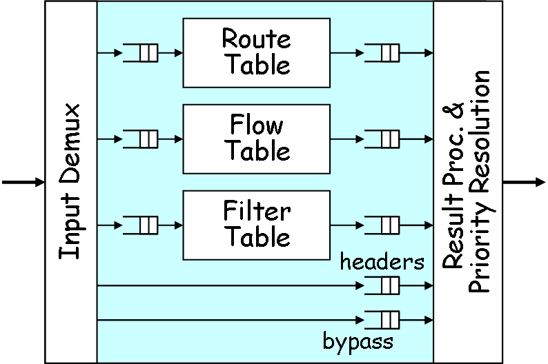
Each engine delivers one or two results to RPPR. The LPM and EM algorithms each select their one highest priority matching filters. The GM algorithm selects the first match highest priority exclusive filter and the first match highest priority non-exclusive filter. Based on these results, RPPR then selects which route, filter or set of filters to apply to the packet. In the case of a non-exclusive filter match, the packet header is copied and delivered to the QMGR. (GM filters in the RLI are normally exclusive filters. However, selecting the aux box in the GM filter panel defines a non-exclusive GM filter.) All EM filters share a single priority. Likewise, all Route Table entries share a single priority. GM filters, on the otherhand, each have their own priorities.
Thus, it is possible that CARL will return four matches for a single packet: an exclusive GM filter, a non-exclusive GM filter (aux), an EM filter, and a Route Lookup entry. But packet forwarding can be summarized as follows:
Each result has a priority level chosen from 64 possible priorities (0-63 with 0 the highest priority). Although they could all have the same priority, identical priority levels should not be used to avoid confusion.
A user indicates plugin processing at a port by installing a filter F at a port's FPX, installing and instantiating a plugin P at the port's SPC, and then binding the filter to the plugin instance. The binding is indicated by a unique QID in the range 8-127. The QID field in the intraport shim of any packet selected by F is set to the binding QID. Then, the packet is placed in the appropriate FPX queue and paced to the SPC over a special VCI (62) with an aggregate rate of 200 Mb/s.
If the aux field of a GM filter is set and the filter is bound to a plugin instance, a copy of the packet is sent to the SPC. This approach is typically taken when the plugin is used for network management where plugins drop the packet after updating statistical counters.
Step 3 (Plugin Processing in the SPC):
An interrupt is generated when a packet arrives to an SPC. Unlike a traditional OS kernel, the SPC processes packets entirely at the device interrupt level. Once an interrupt occurs, all packets that have arrived (data and control) will be processed before interrupts are reenabled.
An arriving packet is demultiplexed to the handle_packet routine of the appropriate plugin instance using the QID in the intraport shim. For example, in the COUNTER plugin, an arriving packet will be passed to the COUNTER_handle_packet routine where it is processed. Examples of packet processing include:
If one or more packets are returned from the handle_packet routine, the packets are passed back to the FPX using VCI 62 and with the QID in the intraport shim increased by 128. If the plugin changed the packet header, the packet will have to be reclassified by the FPX.
Step 4 (Virtual Output Queue/Packet Transmission):
Best effort packets destined for an OPP (and therefore not dropped) are placed in the VOQ associated with the OVIN in the interport shim. The forwarding queue is identified by the QID field in the intraport shim and indicates either a datagram queue or a reserved flow queue. A pacing algorithm rate controls the packets out of the VOQs through the switch fabric and to an OPP. One such algorithm is a Distributed Queueing (DQ) algorithm which attempts to maximize the utilization of the output links in a work conserving manner (an output link is never idle if there are any packets in the NSP that are destined for that output). If the DQ algorithm is disabled (OFF), packets are paced out of their queues according to the quantum parameter of a weighted DRR scheduler.
The interport shim is eight bytes (Fig. 3) and contains four fields. But the one field of interest to a plugin is the Output VIN (OVIN) which indicates the output port where the packet should be forwarded.
Fig. 3. Interport Shim.
The discussion about IPP plugin processing applies to the OPP as well. OPP processing differs from IPP processing in several ways. First, the interport shim must be removed before transmitting a packet over the line card. Second, there is no need for route lookup since no forwarding is done at an OPP. Finally, packets are placed in output queues in preparation for packet scheduling. The set of output queues include 64 best-effort queues and 184 reserved flow queues. Currently, the link packet scheduler implements a weighted DRR (Deficit Round Robin) algorithm which is controlled by a quantum parameter and a threshold parameter. The quantum parameter controls the weight in a DRR scheduler. The threshold indicates the queue size. A packet that will exceed the queue size is discarded.
Revised: Wed, July 12, 2006
| Tutorial >> The ONL Architecture |
|