| Tutorial >> The ONL Architecture |
|
At the core of each NSP (Network Services Platform) is an 8-port ATM switch (Fig. 1). Each port contains an FPX and an SPC (not shown). Arriving IP packets are wrapped inside an AAL5 frame after prepending a shim. The AAL5 frames are forwarded according to VCIs. A frame going from input port P to output port Q will be broken into ATM cells each with a VCI of 64+Q in its ATM header. The internal forwarding table (Virtual Translation Table or VXT) of the ATM switch will send the cells of the frame to port Q after changing the VCI in the ATM headers to 64+P. Upon arrival to output port Q, the sending port can be determined from the VCI since it was modified at input port P. For example, all cells carrying IP packets coming from port 2 but destined for port 3 will use VCI 66. At input port 2, the VCI in the ATM cell header will be modified to 67.
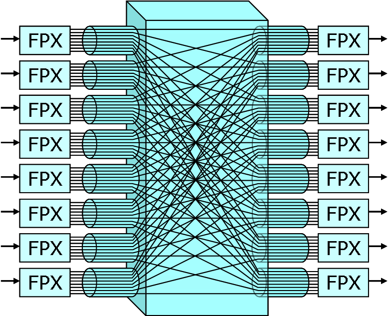
For the moment, consider a 1500-byte IP packet containing a TCP segment where the 1500 bytes includes the 20-byte IP header and 20-byte TCP header. The IPP will prepend a 16-byte interport shim to the 1500 bytes for 1,516 bytes. Since each ATM cell payload is 48 bytes, it will take 32 ATM cells to carry this packet across the switch fabric. Resequencing buffers at the output ports ensures that cells, which may follow different paths through the switching network and be delayed by different amounts of time, are restored to their original order before transmission on the external links.
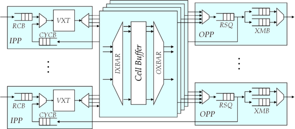
Fig. 2 shows the main logical components of the ATM switch. Note that the IPP and OPP labels here refer to the Input and Output Port Processors of the switch and not the NSP (e.g., the IPP of an NSP refers to the FPX-SPC combination at an input port that injects traffic into an IPP of the ATM switch). When cells arrive on an input link, they are placed in the receive buffer (RCB) to await transmission into the switch fabric. When the switch is ready to accept a cell, the virtual path and virtual circuit identifiers (VPIs and VCIs) from the ATM cell header are used to select an entry from the Virtual Path/Circuit Translation Table (VXT). The entry includes an output port number, and a new VPI and VCI. The VPI and VCI fields in the ATM header are replaced by the new VPI and VCI values from the VXT. Then, the switching network routes the cell to the designated output port where it is placed in the cell Resequencer (RSQ) and then the Transmit Buffer (XMB).
| Tutorial >> The ONL Architecture |
|