| Tutorial >> Router Plugins |
|
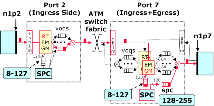
Packets can be sent to the SPC on both the ingress and the egress side of an NSP for custom packet processing by installing an appropriate filter. Fig.1 shows the queues associated with the SPC on both the ingress and egress sides. In this example, packets are shown going to VOQ 7 on the ingress side, then to the SPC on the egress side of port 7, and finally to one of the 128 SPC queues on the egress side of port 7 before going out the link. On the egress side, a packet that is placed in SPC queue k (where k is between 8 and 127) will be placed in queue 128+k when it comes back from the SPC. Note that queues numbered from 1 to 7 are also used to send packets to the SPC but are reserved for the FPX to send exception packets (e.g., bad packet) and cannot be used by the user. Fig. 1 shows both the ingress and the egress side of port 7, but only the ingress side of port 2.

The 120 queues (QIDs 8 to 127) for packets going to the SPC are serviced using the normal Weighted Deficit Round Robin (WDRR) algorithm. A user can parameterize the service provided to these queues through the Queue Table using the same threshhold and quantum parameters used to define packet scheduling for the outgoing link. By default, the aggregate sending rate of packets sent to the SPC is limited to 200 Mbps to avoid overloading the SPC.
The 128 SPC egress queues (QIDs 128 to 255) for packets from the SPC are serviced along with the 64 datagram queues and the 184 reserved flow queues using WDRR.
| Tutorial >> Router Plugins |
|