| Tutorial >> Router Plugins |
|
This page describes how to install and use plugins by describing how to install a delay plugin. Recall that the basic steps involved in installing a plugin are to load a plugin into an SPC, create an instance of the plugin at the SPC, and create a filter to direct packets to the plugin.
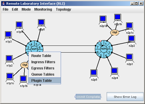
We will send TCP traffic from n1p2 to n2p2 over the top link running from egress port 1.6 to ingress port 2.7. The ACK packets will return over the same link in the opposite direction and through egress port 1.2. We want to install the pdelay plugin at port 1.2 to delay the ACK packets by 50 msec, the default delay of the plugin. Fig. 1 shows how to display the Plugin Table by selecting Port 1.2 => Plugin Table.
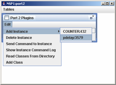
Fig. 2 shows that we have selected Port 2 Plugins => Edit => Add Instance => pdelay:3579 which will load the pdelay plugin and create an instance at port 1.2. The plugin name is pdelay and the plugin ID is 3579. (Later we will see how plugin IDs are assigned.) This plugin is one of the standard (predefined) plugins in ~onl/stdPlugins/. The menu shows that another plugin entry is COUNTER:432. Users can also define their own plugins.
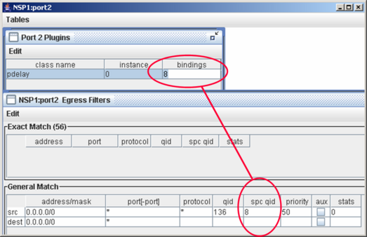
The Add Instance menu item will create a plugin entry in the Plugin Table that must be completed by the user. Fig. 3 shows that we have enterred 8 into the bindings field to indicate that we want the SPC to send all packets arriving to its queue 8 to this instance of the pdelay plugin. The RLI will fill in the instance field after the plugin instance has been created. Again, this cannot happen until after you have defined a filter to send the packets to the SPC and selected File => Commit to tell the system to configure the network.
Fig. 3 also shows that we have added a GM filter with fields that will match any source and destination IP addresses, any source and destination port numbers and any protocol. We have also indicated that the packets will be sent to SPC queue 8. It is this field and the spc qid field that binds the filter to the pdelay instance. The qid field in the GM filter will automatically be filled in with a value of 136 because the qid used by the FPX to send packets to the SPC is 128 more than the SPC's QID; i.e., 136 = 128+8 in this example. Alternatively, you could have enterred the qid of 136 and the RLI would automatically set the SPC QID to 8. If we select File => Commit, the pdelay instance number will be set (0 in this example).
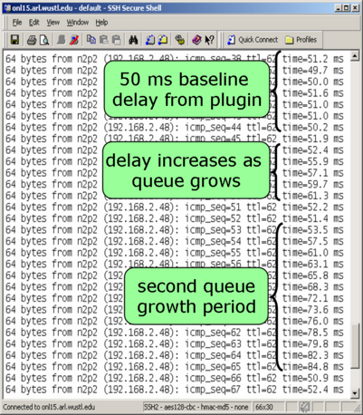
We run the ping command to send ping traffic between n1p2 and n2p2 to check that the delay is in fact atleast equal to the default delay of the pdelay plugin. Fig. 4 shows the results when there are three TCP flows: n1p2-n2p2, n1p3-n2p3 and n1p4-n2p4. The flows start at staggered times as in our earlier examples. Fig. 4 shows not only the 50 msec delay from the pdelay plugin but that as the number of TCP flows increases, so does the queueing delay at the bottleneck link 1.6-to-2.7.
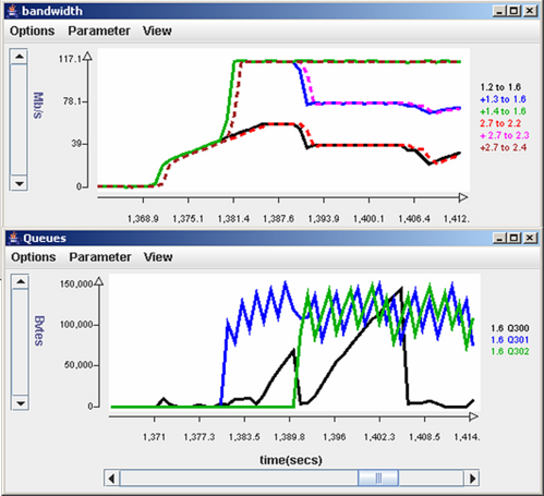
Fig. 5 shows the effect of the pdelay plugin on the bandwidth and queue length of the flow going through queue 300. Recall that the only flow having its ACKs delayed is the n1p2-n2p2 one which gets placed into reserved queue 300 at egress port 1.6. The bandwidth chart shows that the flows attempt to obtain an equal share of the link capacity although the flow between n1p2 and n2p2 through 1.6 and 2.7 suffers at around T = 1408 (black curve). The queue length chart shows that the 50 msec delay causes the control cycle of the flow from n1p2 (black curve) to be substantially longer than the other two flows that are not getting their packets delayed.
| Tutorial >> Router Plugins |
|