| Tutorial >> The ONL Architecture |
|
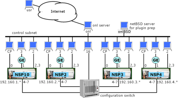
The current equipment configuration for the Open Network Laboratory consists of four experimental routers called Network Service Processors (NSPs) plus 40 rack-mounted PCs that serve as end systems and control processors (Fig. 1). The hardware components are grouped into four clusters with each cluster consisting of a single NSP, a control processor (CP) that manages the NSP, a gigabit Ethernet subnet with three connected hosts, and two directly connected hosts. This leaves four of each NSP's ports uncommitted. These four ports are connected to a Configuration Switch that serves as an electronic patch panel to connect NSPs to each other or to additional hosts. Users interact with the testbed using the RLI, which is a standalone Java application. The RLI communicates with the testbed through the main ONL server which relays messages to the various testbed components. The testbed can support simultaneous sessions by multiple users, so long as there are sufficient resources available. A second server (onlBSD) host is to compile software plugins for the NSPs' embedded processors.
The Configuration Switch is used to implement virtual network topologies linking the routers to one another and to hosts. When multiple experimental networks are present in the testbed, they operate completely independently. The configuration switch has a number of unused ports that we plan to use to deliver additional features in the future, such as programmable link delays and high rate traffic generators.
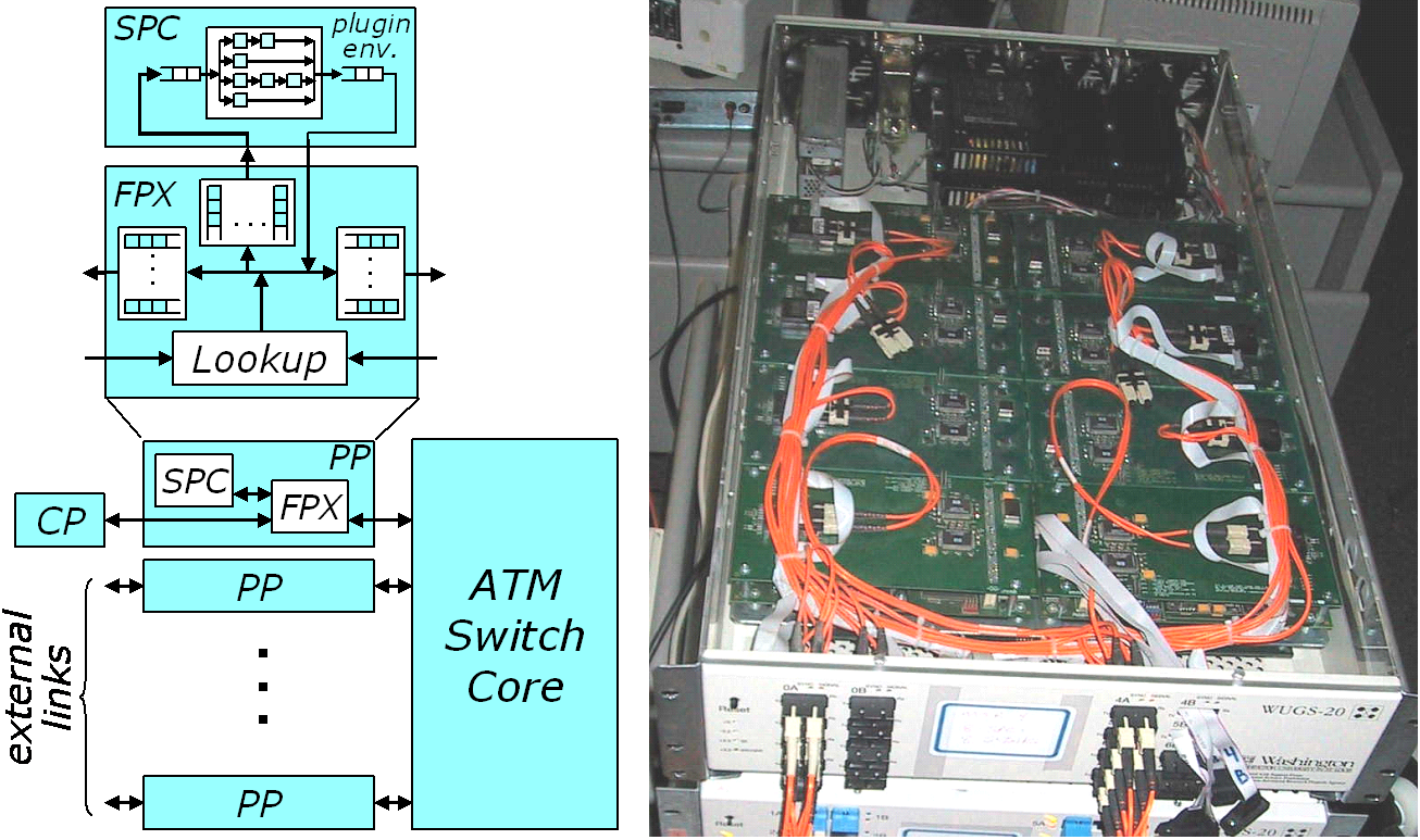
The core component of our testbed is a modular, gigabit router (Fig. 2). The system uses a cell-switched core and the per port interface hardware includes an embedded processor subsystem, called the Smart Port Card (SPC), and a programmable logic board, called the Field Programmable Port Extender (FPX), which includes a large field programmable gate array, with four high speed memory interfaces providing access to 2 MB of SRAM and 128 MB of DRAM. The system supports several different types of line cards, including one for gigabit Ethernet (GigE). The core cell switch supports 1024 virtual circuits per port, per virtual circuit traffic monitoring, support for multicast and two hardware priority levels. One port of the system is typically used by an external control processor for system management through in-band control cells.
Packets entering the system pass first to the FPX, which can be configured to do IP routing, flow classification and packet scheduling. Packets that require software processing can be diverted to the SPC on either the input or output side of the system. The system uses a modular design that allows easy insertion of add-on cards like the FPX and SPC. Such cards are equipped with connectors at either end and are stacked on top of one another. This makes it easy to upgrade individual pieces and to configure systems with a variety of characteristics.
The SPC includes a dual port network interface chip (the ATM Port Interconnect Controller or APIC), which allows any portion of the traffic entering or leaving the system to be diverted to the Pentium processor module on the card. The APIC transfers IP packets directly to and from processor memory over a 32 bit PC bus. In situations where 10% of the link traffic requires software processing, the SPC allows the execution of close to 50 instructions per byte, which is sufficient to implement moderately complex applications that examine and modify the packet data.
The FPX contains two field programmable gate arrays.
The Network Interface Device (NID) can be used to redirect any
portion of the arriving traffic to the Reprogrammable
Application Device (RAD), which is a Xilinx XCV2000E, with 80 KB
of on-chip SRAM and 38,400 basic logic blocks, each containing
one flip flop, a configurable four variable logic function
generator and miscellaneous support circuits.
The RAD is equipped with 2 SRAMs and 2 SDRAMs, which can operate at
up to 100 MHz, giving it a raw memory bandwidth of up to 2.5
GBytes per second.
The available resources allow it to support
all the core packet processing functions required of an
advanced router supporting gigabit link speeds.
The FPX supports dynamic reconfiguration of the RAD.
A complete new RAD
configuration can be downloaded in just a few seconds.
| Tutorial >> The ONL Architecture |
|