| Tutorial >> Filters, Queues and Bandwidth |
|
The RLI also provides the user access to more advanced features of the hardware such as packet classification, queueing and redirection, bandwidth sharing and configurable parameters (e.g., link capacity). This section describes a simple experiment in which UDP traffic from multiple sources flowing through a bottleneck link are given different shares of the link bandwidth. The real-time display capability is used to verify that the system behaves as expected. Throughout this section, architectural features of Network Service Processors (NSPs) are described more fully in the companion section NSP Architecture.
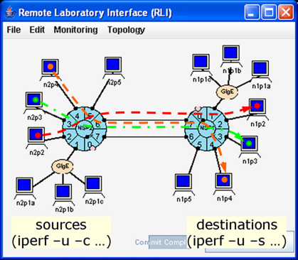
The experiment uses the two-NSP topology described in the previous section, but instead of sending ping traffic, we use the iperf utility to send UDP traffic from the three hosts n2p2, n2p3 and n2p4 to hosts n1p2, n1p3 and n1p4 through the bottleneck link joining port 6 of NSP 2 to port 7 of NSP 1. We examine three cases in which the three flows are mapped to:
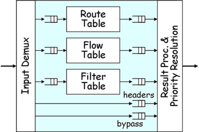
The default behavior at an egress port is to place packets in FIFO datagram queues based on a hash function computed over parts of the IP packet header. However, the FPX has three parallel lookup tables at each port (Fig. 1): 1) a Route Table that uses longest prefix matching, 2) a Flow Table that uses Exact Match (EM) filters, and 3) a Filter Table that uses General Match (GM) filters. Both EM and GM filters match on five fields of a packet's IP header: the source and destination IP address fields, the source and destination transport layer port fields, and the protocol field. But GM filters differ from EM filters in two respects: GM filters allow wildcarding of any of the fields, and each GM filter has an assignable priority. When a packet matches multiple filters, the highest priority entry is chosen. In order to give special treatment to the three flows, we use the Filter Table in the FPX to redirect the three flows to separate reserved queues.
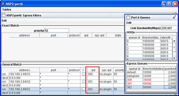
Fig. 3 shows the GM filters used to direct three flows to queues 300-302 respectively at egress port 6. Each of the source address/mask fields match the interfaces of the three sending hosts, and the destination address/mask fields match packets going toward the subnets associated with NSP 1. We have wild-carded the application port fields and the protocol field (even though we will be sending UDP traffic in most cases).
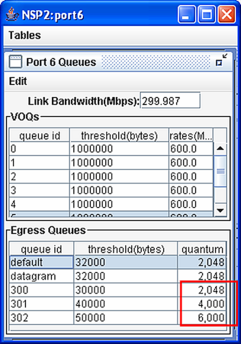
Fig. 4 shows the configuration parameters for the queues at port 6 of NSP 2. Since each port handles traffic in both directions, the parameters for ingress and egress sides are shown. In this experiment, the egress link capacity was enterred as 300 Mbps, but the commit process set the actual link rate to 299.987 Mbps (explained later). Since the internal switch capacity (not shown) has been set to 600 Mbps, there is a 2:1 switch speed advantage. The link bandwidth can be set to any rate up to 1 Gb/s.
The VOQs table contains the eight VOQs on the ingress side. Recall that packets in VOQ k are destined for output k. The threshold column indicates the discard threshold; i.e., the queue level (in bytes) above which arriving packets for that queue are discarded. The threshold has been set to the default value of 1,000,000 bytes. The rates column indicates the rate at which packets are transmitted from the VOQ when there is a backlog in the VOQ. The rate for each VOQ has been set to the default value of 600 Mbps. As described in a later section, it is also possible to have a Distributed Queueing (DQ) algorithm automatically determine the sending rate of the VOQs so as to avoid output link overload while minimizing output link underload.
The Egress Queue table shows the three reserved flow qids (300-302) and the datagram queues. There are actually 64 datagram queues. If a packet arrives to an egress port and does not match an EM or GM filter, it will be be placed in one of these 64 datagram queues based on a hash function. However, EM and GM filters can be used to place packets in one of the reserved flow queues (qids 256-439). In this example, the flows are placed in queues 300-302. The relative values of the entries in the quantum field for the three reserved flow qids indicate the bandwidth shares of a Weighted Deficit Round Robin (WDRR) packet scheduling algorithm. The desired bandwidth ratios of queues 300-302 are approximately 1:2:3 (i.e., 2048:4000:6000) which gives the most bandwidth to queue 302. If there were packets also in the datagram queues, the quantum fields in all non-empty queues would determine the share of the 300 Mbps link that each queue would receive.
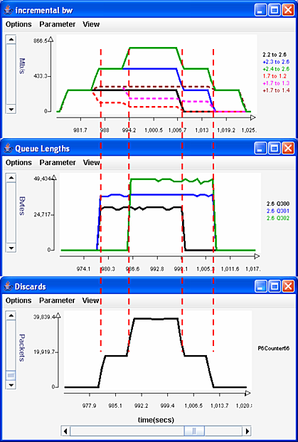
Fig. 5 shows three plots. The top plot shows the bandwidths in incremental form. Specifically, the first solid curve shows the bandwidth entering the bottleneck link coming from the first flow, the second solid curve shows the bandwidth contributed by the first two flows and the third shows the total bandwidth contributed by all three flows. The dashed curves show the bandwidth leaving the bottleneck link. Note that the three sources are sending at an aggregate rate of over 750 Mbps, well over the 300 Mbps capacity of the bottleneck. The dashed curves indicate that the three UDP flows are receiving bandwidth in the proportion 1:2:3 when all three flows are active (middle section) and 2:3 (right end) when only qids 301 and 302 have packets. The middle plot shows the queue length of the reserved flow queues and that the length of the three reserved flows is in the ratio 3:4:5 as required by the threshold settings. The bottom plot shows the number of packets discarded at port 2.6 due to overflows of queues 300-302 at egress port 2.6.
Filters can also be used to re-direct individual flows or
flow aggregates to different outgoing links than those
specified by the routing tables.
GM filters can also be configured
to replicate matching packets and direct the copies
to a different location which
is useful for passive monitoring of a flow.
Revised: Fri, July 21, 2006
| Tutorial >> Filters, Queues and Bandwidth |
|