| Tutorial >> Filters, Queues and Bandwidth |
|
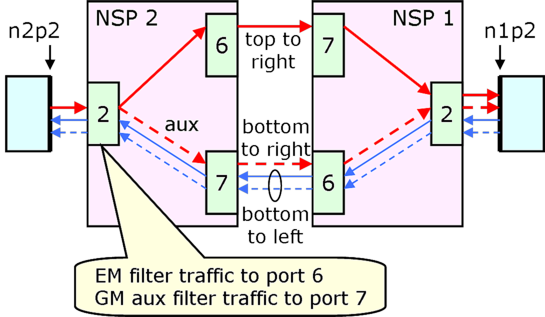
This page demonstrates the basic features of flow tables and filter tables; i.e., Exact Match (EM) filters and General Match (GM) filters. We use again the 2-NSP configuration from the preceding example (Fig. 1). Note that NSP 2 is on your left, and NSP 1 is on your right. Recall that the routing tables at every port have default entries except that there are extra entries for paths between NSPs. For example, at port 2.2 (NSP 2, port 2), there is a route entry of (192.168.1.0/24, 6) which will route all packets from host n2p2 through the top link 2.6-1.7; i.e., all packets destined for any interface on NSP 1 will go out port 2.6 (NSP 2, port 6) to port 1.7 (NSP 1, port 7). We will show how to override the route table entries using first an EM filter and then a GM filter.
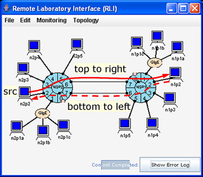
We will override the route table entries with an EM filter so that ping packets from port 2.2 will flow over the bottom link 2.7-1.6 instead of the top link 2.6-1.7.
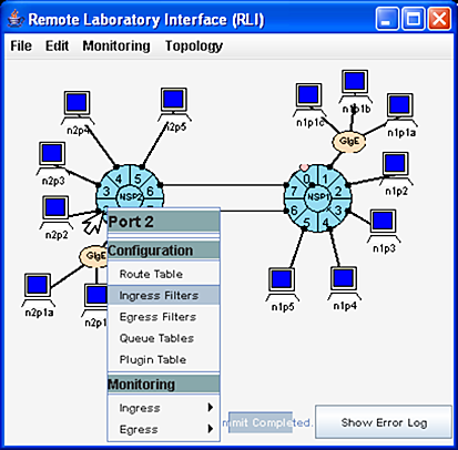
In Fig. 2, we select port 2.2 => Ingress Filters to open up a panel for the tables at port 2.2. The NSP2:port2 window will appear showing the NSP2:port2 Ingress Filters panel similar to the one shown to the rear of Fig. 3. The other menu entries in Fig. 2 provide access to the Route Table, Egress Filters, Queue Tables and the Plugin Table which will be described later. To also show the Routing Table, select NSP2:port2 => Tables => Routing Table.
We want to add an EM filter entry to the Flow Table that will match all ping packets from port 2.2 going to any interface at NSP 1 and force it to go through port 2.7. To do this, we must:
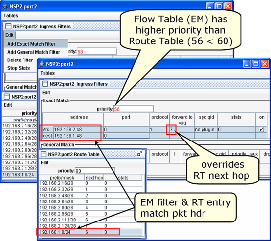
The top panel in Fig. 3 shows the result of the following operations:
We commit the changes ( Select File => Commit ), and proceed to test the filter. We will test our filter using one ping traffic generator that sends traffic from n2p2 to n1p2 ( ping recipe) and monitoring the incoming and outgoing traffic at ports 2.6 and 2.7 ( monitoring recipe).
If the EM filter were not installed, the ICMP echo request packets would travel along the top link 2.6-1.7 to the right and the returning ICMP echo reply packets travel along the bottom link to the left. On the other hand, if the EM filter was installed, we should see the ICMP echo request packets travel along the bottom link 2.7-1.6 to the right and the returning ICMP echo reply packets still travel along the bottom link to the left since the filter only affects the ICMP echo request packets.
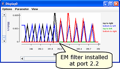
Fig. 4 shows the traffic plot when the EM filter is installed at around T = 352. Prior to filter installation, traffic appears on the top to right and the bottom to left plots. But when the filter is installed, we still see return traffic on the bottom to left plot, but now we see traffic on the bottom to right plot instead of the top to right plot. ICMP echo request traffic is now flowing to the right along the bottom 2.7-1.6 link, and the ICMP echo reply traffic is still flowing to the left along the bottom 1.6-2.7 link. There is still no traffic flowing along the top-to-left link.
Now, we will show how to override the EM filter entry with a GM filter so that ping packets from port 2.2 will again flow over the top 2.6-1.7 link instead of the bottom 2.7-1.6 link.
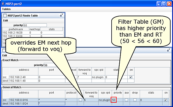
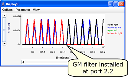
Fig. 6 shows that the GM filter was installed around T = 385 and has overridden the EM filter. The traffic is again flowing to the right along the top link (top to right) after T = 385.
A GM filter can also be configured to replicate every packet it matches. Replication might be useful in creating a duplicate traffic stream that is sent to a host or plugin for further analysis. In this section, we only illustrate how to duplicate packets.
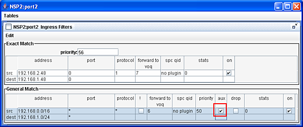
Fig. 7 shows that a GM filter can be configured to duplicate the ICMP echo request packets by checking the aux box which defines an auxiliary GM filter. The term auxiliary is meant to indicate that more than one packet may be forwarded. In this example, a Route Table (RT) entry and the EM filter also match the ICMP echo request packets. But since the EM filter has higher priority than the RT, it will determine the disposition of the other copy of the packet. The end effect is that one copy of the packet will go to port 2.6 because of the auxiliary GM filter, and the other copy will go to port 2.7 because of the EM filter.
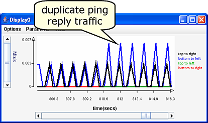
Fig. 8 shows the result of checking the aux box. (You should compare Fig. 8 to the other traffic plots on this page.) At T = 810, the GM filter was installed, and now, traffic flows to the right on both the top 2.6-1.7 link (top to right) and the bottom 2.7-1.6 link (bottom to right) between the two NSPs. (The bottom to right plot is hidden behind the top to right plot.) Furthermore, note that the traffic volume on the return path over the bottom link (bottom to left) is about 6 Kb/s or twice the return traffic volume as before. That is because there is now twice as many ICMP echo reply packets as before: one for each original packet and one for each copy. This situation is shown in Fig. 9.
Revised: Mon, July 31, 2006
| Tutorial >> Filters, Queues and Bandwidth |
|