| Filters, Queues and Bandwidth >> NSP Architecture |
|
Packets are held in queues as they move from one NSP port to another. Fig. 1 shows 256 of the 512 FPX queues that a packet can encounter as it moves from n1p2 to n1p7. The 256 queues associated with the SPC are not shown and will described in the section on router plugins.
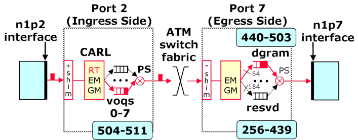
When a packet enters the ingress side of an NSP, it will be placed in one of eight VOQs (Virtual Output Queues) as it awaits transmission to the appropriate output port. All packets destined for output port k are placed in VOQ k and are serviced in FCFS order. This arrangement prevents head-of-the-line blocking that is found in systems using only a single queue since packets destined for output port k do not have to wait on packets going to any other output ports. The eight VOQs correspond to internal queues numbered from 504 to 511. The VOQs are serviced by a Distributed Queueing (DQ) algorithm if DQ is turned ON or by rate controlled token buckets if DQ is turned OFF.
After the packet gets to the egress side (output port), it will normally be placed in one of 64 datagram queues numbered from 440 to 553. The specific datagram queue is determined by a hash function. However, the user can install a filter that directs the packet to one of 184 reserved flow queues numbered from 256 to 439. The user can give preferential treatment to a reserved flow queue by setting its quantum field in the Queue Table higher than another flows quantum value.
The egress queues are serviced by a Weighted Deficit Round Robin (WDRR) algorithm which replenishes each non-empty queue's deficit counter with its quantum value. For example, suppose we set the quantum value for reserved flow queues 300 and 301 to 2,048 (the default) and 4,096 respectively. These settings will result in flows to queue 301 getting double the service rate given to queue 300. While each queue's quantum determines each queue's relative service rate, a token bucket (described in the Link Rate page) controls the transmission rate of the link.
A user can easily monitor the length of any of these queues through the
RLI by selecting the port and then either Ingress => VOQ Length
for a VOQ length or Egress => Queue Length for an egress queue
length.
It is easy to monitor reserved flow queues because the user selects
a queue in the range 256 to 439 and defines a filter that will match
the desired packets and queue them appropriately.
Datagram Hash Function
A packet going to one of the 64 datagram queues is determined by the following algorithm:
Extract Address Components:
	sa[]	= c0 a8 02 30 (hex)	= sa[31:24] sa[23:16] sa[15:8] sa[7:0]
	sa[9:8]	= 2 (hex) = 10 (binary)		since	sa[11:8] = 02 (hex)
	sa[6:5]	= 01 (binary)			since	sa[7:0]  = 30 (hex)
	da[6:5]	= 01 (binary)			since	da[] = c0 a8 01 30 (hex)

Compute H:
	H	= 10 01 01 (binary)
		= 32 + 4 + 1 = 37 (decimal)
Compute QID:
	QID	= 440 + 37 = 437
| Filters, Queues and Bandwidth >> NSP Architecture |
|