| Filters, Queues and Bandwidth >> NSP Architecture |
|
The rate at which IP datagrams leave an egress port is controlled by a token bucket regulater in the FPX. When a user enters a rate r in the Queue Table for the link rate, the user is defining the token bucket that controls the effective transmission rate of the link attached to the egress port.
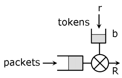
In Fig. 1, R is the maximum rate of the link (1 Gbps in our testbed).
A token bucket operates as follows. A bucket is filled at a rate of r tokens per second. If the bucket is full, an arriving token is discarded. When a packet of length L arrives to the token bucket, it is allowed to proceed and L tokens are removed from the bucket if the bucket contains atleast L tokens. Otherwise, the packet is queued. Thus, a token bucket is defined by two parameters:
Note that when the packet is selected for transmission, it will go out at the maximum rate of the link (1 Gbps) independent of the user's link rate setting. A link rate set to r means that there will be a 1 Gbps burst followed by enough idle time so that the transmission rate computed over the combined transmission and idle periods is r.
In the ONL testbed, the token bucket depth is set to two MTUs (Maximum Transmission Units) or 4,096 bytes. If a token bucket has been idle long enough to fill the bucket, this setting can result in possibly two unexpected behaviors when a packet stream is examined closely:
The unexpected behaviors described above are invisible for the most part because most experiments measure traffic at large enough time intervals where the behavior is not apparent. But a project that uses a technique such as packet pair will encounter this behavior since it involves measuring interpacket times.
The actual link rate may also differ from than the user's desired link rate because of the FPX's link rate implementation algorithm. In fact, the actual link rate will be:
r = Max { 61, 61 * k } Kbps
where k is the largest integer such that 61*k is no larger than R.
In the actual implementation, tokens are added at each FPX clock
tick (not continuously), and each token represents some number of
bytes.
In Fig. 1, we showed the token bucket regulating a single queue. In reality, the token bucket cycles through all of the egress queues in round-robin fashion. As it visits each active queue (a queue with atleast one packet), it adds the queue's quantum to the queue's deficit counter and transmits a packet from the queue if the deficit counter is atleast as large as the next packet's length and the token bucket has enough tokens. The token bucket repeats this process until it no longer has enough tokens to send a packet.
| Filters, Queues and Bandwidth >> NSP Architecture |
|